Screw chillers with refrigerant 1234ZE

Since the beginning of the 21st century and especially in recent years, climate change has become humanity’s greatest environmental threat. Ecologists and scientists try to warn both society and the industrial sector of the climatic changes that are expected if we do not considerably reduce the emission of greenhouse gases and the use of fossil fuels.


In this sense, the refrigeration and air conditioning industry has had to evolve towards the study and use of new refrigerants. According to a study by the German Federal Environment Agency, in 2004 fluorinated gases emitted by the refrigeration/air conditioning industry were responsible for 1.3% of global warming and an increase of up to 7.9% was estimated by the year 2050.

Influence of the refrigeration sector on the emission of fluorinated gases.

Evolution of refrigerant gases

The evolution of refrigerant gases began in the 1970s and continues to this day:

  • In 2000 the sale and use of chlorofluorocarbons (CFCs) such as R11 and R12 were banned. Chlorine reacts with ozone contributing to the destruction of the ozone layer. Furthermore, they are greenhouse gases with a GWP of 3,800 and 8,100 respectively.
  • The ban on hydrochlorofluorocarbons (HCFCs) was more progressive, as can be seen in the following image. Its use being totally prohibited in 2015. The most significant HCFCs are R22 and R123, with a GWP of 1700 and 5000 respectively.
  • Hydrofluorocarbons (HFCs) are part of the third generation, which were created to replace CFCs and HCFCs. In principle they were considered ecological, since they did not contribute to the destruction of the ozone layer as they did not contain chlorine. However, fluorine converts them into greenhouse gases. Among the most prominent are R410 and R134A, with a GWP of 2088 and 1300 respectively.

Fig.1: Energy Efficiency Master Control of Industrial Processes, UCO.

For all the aforementioned, the refrigeration sector is obliged to investigate and develop new alternatives that allow working with refrigerants with similar thermodynamic properties and zero GWP levels, in order to reduce greenhouse emissions into the atmosphere.


In the fourth generation of refrigerants are HFOs (hydrofluorolefins). According to D. Sánchez and I. Arauzo, these gases have good thermodynamic characteristics, although the cooling capacity is less than that of HFCs by at least 5%, they do not affect the destruction of the ozone layer and they have a very low GWP. Among the most prominent is the R32 and 1234ze. Both are considered A2L gases, that is, slightly flammable. Therefore, although there are some considerations for their use, they make them good alternatives to HFCs.


Investigations lead to the use of inorganic gases such as R717 (NH3 and CO2). Among the main advantages of these refrigerants we can highlight that they have thermodynamic yields around 3-10% higher than that of the aforementioned gases. In addition, the GWP and the ozone depletion potential is between 0 and 1, so at first glance they could be considered ideal gases for this sector. However, each of them has different disadvantages.

  • NH3 (R717). It is not compatible with copper. In addition, it is a toxic and somewhat flammable component. This implies that the costs of equipment and facilities increase considerably before the need to increase security.
  • CO2 (R744). The working pressures are much higher, which requires greater control of equipment and facilities, which increases costs. In addition, being heavier than air, it displaces O2 to dangerous levels for health. As it is odorless, the leaks are not noticeable. This causes that the securities are extreme and therefore the costs much higher.


Therefore, focusing the comparison between HFO and inorganic refrigerants, currently the trend tends to be positioned by HFOs, leaving inorganic ones destined for installations where the cooling capacity is very high.
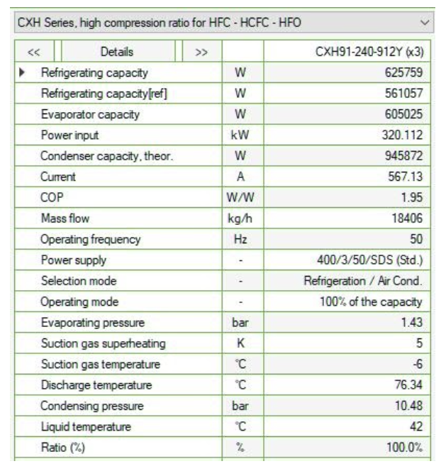
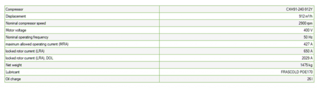
Throughout the article, a real case of a flatbed chiller with HFO refrigerant and the techniques used to reduce its energy consumption will be shown.

Description of chiller plant and installation

In equipment with high cooling capacity and medium working temperatures, the use of 1234ze as an alternative to R134A or R410A is increasing. This article will show operating data of a Keyter Pangea range chiller plant with 531.9 kW of cooling power in working conditions Water I / O temperature -2 / -6 ºC and outside temperature 35 ºC. It is a KWT8285L model equipment, installed on the roof of a food industry, which serves six cheese storage chambers and a drying room.


One of the peculiarities of the 1234ze refrigerant is that it cannot be used with scroll compressors, so the full cooling capacity is supplied with high-power screw compressors. In this specific case, the equipment has two circuits with one screw compressor per circuit. Although the refrigerant used is A2L, as it is located on the roof and completely outdoors, it is not necessary to increase the leak detection measures, it will only be necessary to take into account the necessary preventive measures regarding the handling of A2L gases for the tasks equipment maintenance.


Due to the slight reduction in the cooling capacity of 1234ze compared to 134A, the components of the refrigeration circuit such as evaporators and condensers of equipment with 1234ze refrigerant will require a larger area than those installed in equipment with 134A. This will mean a higher volume of refrigerant required per circuit and consequently a higher energy consumption at startup compared to equipment with 134A refrigerant.


Considering what is indicated in the previous point, an important aspect of this range of equipment in terms of energy, economic and environmental efficiency is the power absorbed from the equipment. Although the efficiency is calculated under nominal operating conditions, these compressors have a high energy consumption at start-up. Despite the fact that in the study of thermal loads of the facilities and the equipment controls are designed to reduce the number of equipment starts, it is important to use efficient alternatives that help control these high consumption peaks at startup. Furthermore, it is very common to find industrial areas with electrical power limitations, so in order to install this type of cooling plants it is necessary to control consumption at startup to avoid significant drops in voltage and power factor.

Types of motor starts

The starting of high power motors can be done directly, by star / delta commutation or with soft starters. In the chiller plant studied, Frascold compressors model CXH91-240-912Y are used, which in the following working conditions would present the technical characteristics indicated in tables 1 and 2.

  • T evaporation = -11ºC
  • T condensation = 52ºC
  • Superheat = 5 K
  • Subcooling = 10 K

Fig.2: CXH-91-240-912Y compressor technical characteristics.

Fig.3: CXH-91-240-912Y compressor technical characteristics.

  • Direct start. Induction motors have a high direct starting current. Depending on the motor variant, it can be 3 to 15 times greater than the nominal current, and more typically a value of 7 to 8 times the nominal current can be assumed. It is recommended for low power ranges (<7.5 kW).
  • Star-delta start. For higher power ranges (> 7.5 kW). It is often used for basic applications. Suitable for safety applications thanks to galvanic isolation.
  • Soft starter. It is used for high power ranges (> 7.5 kW). It is used for more complex applications that require induced torques during starting and stopping.


The following table shows a comparison of the types of starts.

Fig.3: Types of induction motor starts.

If an induction motor is started directly from the mains, the typical evolution of current and torque can damage the supply mains and the driven machine. The SIRIUS 3RW30 and 3RW40 electronic soft starters allow the evolution of current and torque during start-up to be optimally adapted to the requirements of the application. The following graph makes a comparison of both starts.

Fig.4: Comparison of direct induction motor starting, star/delta and soft starter.

In the data shown below, a significant reduction in consumption when starting with a soft starter can be seen of around 50-60% compared to direct starting. However, even though the reduction is very high, in high power engines this consumption is still high. Therefore, in order to significantly reduce consumption at startup, it is best to install a frequency inverter.


Speed ​​control technology – frequency inverter
Variable frequency drives allow the speed of the motor to be controlled by controlling the voltage and the power supply frequency supplied to the motor. Speed ​​control based on load reduces power consumption during equipment operation. In this way, with the frequency inverter not only consumption is reduced at start-up but it is also possible to adapt the operating capacity of the compressor to the capacity required at all times, optimizing more precisely the total capacity of the equipment and controlling the electrical consumption.

Discover the Keyter PANGEA

An inventive and dynamic air-to-water screw chiller.

Data and analysis

Consumption data are taken at startup in the installation of the equipment under study, obtaining the results shown in the following table.

Fig.5: KWT8285 equipment consumption data at startup.

Direct start was not tested at installation, as the chiller’s circuit breaker would trip automatically, since it is 800 A. In addition, starting in this way would cause a very abrupt drop in voltage and power factor. Direct start data is indicated on the motor nameplate and the compressor manufacturer’s technical sheet.


With star/delta starting and soft starter, starting consumptions of 1400 A and 940 A respectively are registered. However, the voltage drops to 330 A and the power factor to 0.3. These voltage and power factor drops are unacceptable for a continuous production factory. For this reason, due to the fact that the power limitations in the installation were very restrictive (1000 KVA transformation center), the only possible solution was the installation of frequency inverters to reduce both the consumption at startup and to adapt the working power of the the compressors to the thermal load of the installation at all times.


The following table shows consumption data at startup and in operation at different values ​​of evaporation and condensation temperature:

Fig.6: Consumption data per compressor based on evaporation and condensation temperatures.

In the table above it is observed that consumption at start-up is not affected by the temperature of the water and outside air. However, the operating consumption of the compressor increases as the evaporation and condensation temperature increases. In the same way, the increase in the condensing temperature implies the increase in the consumption of the condensing fans, since they will increase the operating percentage.


This increase in energy consumption due to the rise in working conditions of the equipment will have a negative influence on its efficiency, since as the absorbed power increases, keeping the supplied cooling power constant, the equipment’s efficiency decreases.

Conclusion

The use of HFO refrigerants as an alternative to HFCs is a good choice, since, although HFOs reduce the cooling capacity by around 5%, the low GWP and the zero destruction of the ozone layer make them refrigerants ideal for use in refrigeration equipment operating at medium temperatures. Some HFO refrigerants like 1234ze cannot be used with multi-scroll compressors.


This fact, together with the aforementioned power reduction and the decrease in density with respect to HFCs, lead to an increase in the refrigerant charges of the equipment, which causes an increase in consumption at the start of the compressors. It is recommended to install frequency inverters to reduce the high consumption at start-up and to be able to adapt the working power of the compressor to the cooling power required at all times.


Keyter Technologies, S.L. continues to work on the development of this technology where it is achieving the desired objective results at the same time as it achieves simple maintenance of the installation. Our R&D department has developed more units of the same model in various locations in Spain and France where demand is currently very high. This type of equipment is also being developed with the optional heat recovery.

More news

Interested in all our news, articles and updates? Read them all and keep yourself updated.

MORE ABOUT KEYTER

What are you interested in?

× WhatsApp